This is my first homebrew hf rig. Its a version of the Michigan Mighty Mite and built for 40 meters. I currently have a 7040 crystal and the rig seems to put out just about 500mw at 7.0405 Mhz. The tone isn't stable and neither is the frequency, but its very exciting to work cw on a rig that consists of 7 parts that you built in an afternoon! Its a great exercise for the novice homebrewer and can be assembled for pretty cheap.
A very quick and easy way to get on the air is to build a "Michigan Mighty Mite" CW transmitter for 160, 80, 40 or 30 meters originated by Ed Knoll, W3FQJ and developed by Tom Jurgens, KY8I. It can't get simpler than this! It has very few parts, costs almost nothing, and it works!
Output power is about 500 milliwatts with a 12-volt power supply. I have measured about 250 mw with a 9v battery as the power source.
Q1: 2N3053, 2N2222, SK3265 or similar inexpensive general-purpose NPN transistor. I use a plastic-case transistor that came in a bargain-pack from Radio Shack - works fine. Use heat sink - try an alligator clip if you don't have a heat sink handy. TANK COIL: use a 1.25" diameter form (35mm film canister, pill bottle, etc.) and #20 - #22 AWG enameled ("magnet") wire. To make tap, wind L1 to the "tapped at" number of turns (see table below). Make a loop about 1 inch long, twist it a few times and finish winding. Sand the insulation off the end of the loop. This is your tap. After winding L1, wrap it with a thin layer of masking tape and wind L2 on top of the tape in the same direction as L1. Secure L2 with more tape and finish by sanding insulation off remaining leads.
 L1: L2:
(primary/collector windings) (secondary/antenna windings)
160m--60 turns, tapped at 20 160m-- 8 turns
 80m--45 turns, tapped at 15 80m---6 turns
 40m--21 turns, tapped at 7 40m---4 turns
 30m--15 turns, tapped at 6 30m---4 turns
XTAL: fundamental-mode crystal for desired frequency. About that variable capacitor - you can salvage one from an old transistor AM Radio or try a trimmer capacitor. Of course, a fullsize variable will work - but it will also be bigger than the rest of the transmitter! Tracking down variable capacitors at a good price is a noble challenge and part of the game. I got mine at Ocean State Electronics for just a couple of bucks. I got the xtal from them as well, but it was not cheap. At $9 it was the most expensive part of the rig!
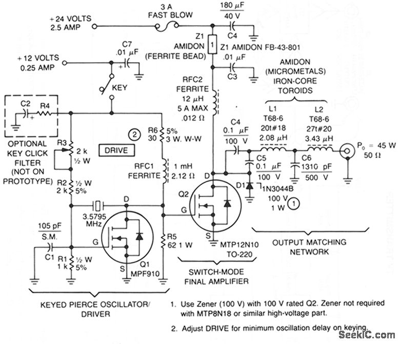
This transmitter consists of a keyed crystal oscillatoridriver and a high efficiency final, each with a TMOS Power FET as the active element. The total parts cost less than $20, and no special construction skills or circuit boards are required.
The Pierce oscillator is unique because the high CRSS of the final amplifier power FET, 700 - 1200 pF, is used as part of the capacitive feedback network. In fact, the oscillator will not work without Q2 installed. The MPF910 is a good choice for this circuit because the transistor is capable of driving the final amplifier in a switching mode, while still retaining enough gain for oscillation.
To minimize cost, a readily-available color burst TV crystal is used as the frequency-determining element for Q1.An unusual 84% output efficiency is possible with this transmitter. Such high efficiency is achieved because of the TMOS power FET's characteristics, along with modification of the usual algorithm for determining output matching.
You can build a power oscillator with an NE592 and some additional parts. Depending on the crystal frequency, RF power generation in the range of 1 to 30 MHz is possible. The parallel resonant circuit C1/L1 must be tuned exactly to the crystal frequency. For final transistors one can use two 2N3906 or BS250 (see QRP push-pull amplifier). RF power output can be adjusted from 20 mW to 1.5 W by varying a common emitter resistor in the push-pull stage.
Do not use this circuit as a transmitter. When keying the NE592 power supply (pin 3) frequency variation (chirp) occurs. If you insist on transmitting with this circuit, then switch the final transistors directly. To do this put a 10 uH choke in series with the key and a 0.1 uF capacitor in parallel. Disadvantages of this circuit are the NE 592 quiescent current (18 mA), the continuously working oscillator and the hard keying.
A broadband output transformer in lieu of the parallel tuned circuit is also worth a try. The 10-ohm emitter resistor, capacitor C1 and the 10 uH choke all disappear if FETS are employed. This design probably represents an all-time low in parts count to achieve 1 watt of linear power output, with only 8 components. Note, however, that the 2N3906's actually produce 50% more output for very little added complexity. We could stop at this point, connecting our 1-watt powerhouse to an antenna (via a low pass filter, of course!), or use this circuit to drive an a RF power transistor of more substantial proportions, as shown below. Depending on the frequency, we can achieve 4 to 6 watts output with 0,5 to 0,75 amps current consumption from our 13.8 VDC supply, using a Japanese bipolar device (2SC2078) intended for CB radio and similar applications.
Fig. 2: MOSFET's and RF power transistor
Transformer T1 matches the relatively low impedance present at the VFO FET gate to the balanced inputs of the NE592. With a unipolar power supply, it is necessary to bias both inputs to roughly one-half of Vcc. Below, we have shown both inputs tied to +6 VDC, conveniently available from the VFO. If 6 volts were not available, we would employ a scheme identical to the "IF amplifier" shown earlier, with Vcc split in half with 2 4,7K-ohm resistors in a divider configuration, applied to both inputs. Normally, stage gain is determined by the value of a resistor between pins 2 & 7. Bench tests reveal better output symmetry, however, if we replace this resistor with a 1 nF capacitor.
Approximately 8 volts of RF drive is available at pins 4&5 if we don't load it too heavily. This is sufficient to drive a pair of 2N3906 PNP transistors in push-pull to roughly 1,5 watts output with excellent efficiency. With bias provided by the NE592, the output transistors are operated in their linear region. Push-pull operation provides inherent suppression of even-order harmonics (2f, 4f, etc.), thereby simplifying our output network design (not shown). T2 is a T44-2 toroid with 5 bifilar primary turns and a single 5 turn secondary. C1 is around 270 pF (for 10 MHz), and should be adjusted to resonate the primary of T2 to signal frequency.
Fig - Schematic of the push-pull final (Pin designations are for the 8 pin DIP package)
A tuned transform tank does not like to see a severely reactive load. An antenna tuner or some other means of cancelling reactance and transforming impedance must be employed if the load departs significantly from 50+j0 ohms. Broadband transformers, on the other hand, are inherently less sensitive to mismatch because of their low Q, but must be backed up with an effective harmonic suppression filter to achieve acceptable spectral purity. A single pi-network should do it. A low Q parallel-resonant circuit (low L, high C) was also tried, with acceptable results.
![]()
This FM transmitter is simple using a single transistor. It provide very clear wireless sound transmission through an ordinary FM radio over a remarkable distance. I've seen lots of designs through the years, some of them were so simple, some of them were powerful, some of them were hard to build etc.
Here is the last step of this evolution, the most stable, smallest, problemless, and energy saving champion of this race. Circuit given below will serve as a durable and versatile FM transmitter till you break or crush it's PCB. Frequency is determined by a parallel L-C resonance circuit and shifts very slow as battery drains out.
Main advantage of this circuit is that power supply is a 1.5Volts cell (any size) which makes it possible to fix PCB and the battery into very tight places. Transmitter even runs with standard NiCd rechargeable cells, for example a 750mAh AA size battery runs it about 500 hours (while it drags 1.4mA at 1.24V) which equals to 20 days. This way circuit especially valuable in amateur spy operations.

Transistor is not a critical part of the circuit, but selecting a high frequency/ low noise one contributes the sound quality and range of the transmitter. PN2222A, 2N2222A, BFxxx series, BC109B, C, and even well known BC238 runs perfect. Key to a well functioning, low consumption circuit is to use a high hFE / low Ceb (internal junction capacity) transistor.
Not all of the condenser microphones are the same in electrical characteristics, so after operating the circuit, use a 10K variable resistance instead of the 5.6K, which supplies current to the internal amplifier of microphone, and adjust it to an optimum point where sound is best in amplitude and quality. Then note the value of the variable resistor and replace it with a fixed one.
The critical part is the inductance L which should be handmade. Get an enameled copper wire of 0.5mm (AWG24) and round two loose loops having a diameter of 4-5mm. Wire size may vary as well. Rest of the work is much dependent on your level of knowledge and experience on inductances: Have an FM radio near the circuit and set frequency where is no reception. Apply power to the circuit and put a iron rod into the inductance loops to chance it's value. When you find the right point, adjust inductance's looseness and, if required, number of turns.
Once it's OK, you may use trimmer capacitor to make further frequency adjustments. You may get help of a experienced person on this point. Do not forget to fix inductance by pouring some glue onto it against external forces. If the reception on the radio lost in a few meters range, than it's probably caused by a wrong coil adjustment and you are in fact listening to a harmonic of the transmitter instead of the center frequency. Place radio far away from the circuit and re-adjust.
This amplifier is based on the transistor 2SC1970 and 2N4427.The output power is about 1.3W and the input driving power is 30-50mW.You can use other transistor as 2SC1971 and get much more output power.1.3W will still get your RF signal quit far and I advice you to use a good 50 ohm resistor as dummy load.Make sure it can take up to 5-10W, else it will be a hot resistor.You MUST use an antenna or 50 ohm dummy resistor while testing else you burn up the transistor.
In all RF system and specially in RF amplifiers, it is very important to have a stable power supply and making sure you won’t get any RF out on the power line. The Capacitor C12 and C13 will stabilise the DC power supply. L1, C10, C11 and L3 with C8, C9 will also prevent RF from leaking out to the powerline and cause oscillation or disturbances. L1 and L3 should be ferrite chokes or inductance’s about 1 to 10 uH.
Transistor Q1 will act as a buffer amplifier, because I don’t want to load the previous stage to much.The input RF signal is passin C1 and F1 which is a small ferrite pearl where the wire just passing through.F1 with C2 will act as an impedance matching for Q1.F1 can be substituted with a coil as L4, but in my test I found that the ferrite pearls gave best performances.L2 is nit a critical component and any coil from 2-10uH will do the job. Q1 will amplify the input signal from 50mW to about 200mW.Q1 can amplify much more, but It doesn’t need to do that because 200mW is good for the final transistor.If you want higher power you can decrease the resistor R2.
If you look at Q2 you will also find a ferrite pearl F2 at the base to emitter. This ferrite pearls is to set the DC voltage to zero and be a high impedance for RF signals. I wounded the wire 4 times around this small ferrite pearl. You can substitute it with a coil of 1uH or more.C4, C5 and L4 forms an input matching unit for the transistor. Not much we can do about that…At the output of the final transistor Q2 you will find 2 coils L5 and L6.
Together with C6 and C7, they form an impedance unit for the antenna and also for the transistor.

Ham Radio (amateur radio) is a popular hobby amongst electronics enthusiasts all over the world. Basically the hobby involves a person in making his own gear consisting of a receiver and transmitter or a transceiver (a receiver and a transmitter in one unit) after procuring a licence from the Ministry of Communications. Home brewing or self construction, an integral part of the hobby, has been sadly neglected in our country, despite the fact that various institutions with governmental help have come into being recently.
Hams aboard can buy the latest transceiver off the shelf at a reasonable price and go on the air immediately. But in India, with a sixty per cent duty involved (now changed?), a commercial transceiver would cost a whopping Rs: 50,000. Hence, it is beyond the reach of an average Indian Ham.
The Indian ham is often handicapped for want of ham gear. To overcome this shortcoming a small receiver and a transmitter can be home brewed with indigenously available components. The total outlay may not exceed a few hundred rupees. Some of you may wonder if this is feasible with out fancy test equipment like oscilloscopes and LC bridges etc. Yes it is possible.
This is a simple AM Transmitter Circuit, but Its very powerful one. It can transmit SW range signals within 13Km circular area. Use external antenna for best results. I recommend to use 12V battery as the power supply. If you hope to using 12V AC-DC adapter you may want to keep very smooth DC out put using stabilizer, unless it will generate low frequency hum when listening to radio out put. Better to read following instructions before assembling the circuit.
>
> L1 Coil
Use 22SWG copper wire and make 10 turns, Insert a ferrite rod in to the coil. see figure 1.
>> L2 Coil
Use 22SWG Copper wire and make 10 turns. Don't use a ferrite rod. Coil diameter is 0.6 cm ( 1/4' ).
>> X-tal (Crystal)
Use 4.4333MHz crystal.


I think that this circuit was developed by G3ROO but my notes are lacking in this information
COMPONENTS LIST
L2,L3 23 turns on a T37-2 Toroid
L1 2 off FX1115 beads side by side with as many turns through as possible
X1 3.5 Mhz Xtal
Relay 12v
Diode across relay 1N4148
Steve, G4RAW described this simple transmitter for 80 metres in Sprat 82 and describes how the World record for building a rig , actually a Oner, and having a QSO, is under 15 minutes.
The circuit shown above uses only a handful of components and the only adjustment is the 1000pF preset capacitor, which is used to attain the best note consistent with power out.
How quick can you make one and have a QSO? Say ten minutes to build and 5 minutes for a contact ... or less?
How about a little competition? Let me know what your time is and I'll put the results on qrp-l and gqrp-l!
Have Fun!
Frank, G3YCC
C1 = 47PF : C2, C3 = 1500PF : C4 = 0.01mfd : C5, C7 = 0.1mfd : C6, C12 = 0.047mfd : C8, C10 = 820PF : C9 = 1500PF : R1, R2 = 5K1 : R3, R5 = 100R : R4 = 180R : R6 = 1K2 : RFC = 22 MICROHENRIES (APPROX) : L1,L2 = 2.2 MICROHENRIES (21 TURNS ON T50-2) : T1 = 2N2369A : T2 = CB OUTPUT TRANSISTOR (2SC1237 OR SIMILAR) : XTAL 3.579MHZ (CHEAP COLOUR TV CRYSTAL) OR 3.560MHZ (QRP CW FREQUENCY)
This simple circuit will give about 1.2 Watts of output when powered from a 13.8VDC supply. If you don't have a 2SC1237, try any other 12V CB radio output transistor 2SC1969, 2SC1307 etc. The value of RFC is not critical, 10 turns on a high permeability ferrite toroid core works fine. I used a DPDT switch for the RX/TX switching, one pole for the aerial (antenna), the other pole to switch the 13.8V supply.

The OSCILLATOR is build arround gate A of IC1. R1, C2 and C3 act as the feedback network and with C1 the frequency can de adjusted a few kHz. By pulling the connection 'TX' to ground the oscillator is started. By replacing the crystal Q1 by a 3.58mhz ceramic resonator the frequency can be adjusted about 50kHz with C1. With C1 the frequency can only be increased, so the frequency range is from 3.58MHz to 3.63MHz. To get the complete range below 3.6MHz a small inductor in series with C1 is needed. The disadvantage of a ceramic resonator is a reduced frequency stability. If temperature changes are avoided (mount T1 on a sufficient large heatsink) and C2 and C3 are 'NP0' condersors a good frequency stability can de acieved. Due to variations between different crystals it might be nessecary to replace C3 by a smaller avlue (10 to 100pF) if the oscillator is not running stable. Also if using a ceramic resonator adjustment of C3 can be required.
The DRIVER is very straightforward. The 3 remaining gates of IC1 are put in parallel. They act as a buffer between the oscillator and PA and also provide a sufficient drive current for the PA. By pulling the connection 'KEY' to ground the transmitter is keyed. NEVER KEY THE TRANSMITTER IF THE OSCILLATOR IS NOT RUNNING !!! In this case T1 will shortcircuit the supply voltage. The FET might survive this, but most likely the power supply and/or L1 will not.
As PA a fast switching FET in is used in classe C. the PA has an effienciency of 60 to 70% and the FET is almost indestructable. For antenna impedances between 20 and 100 Ohm the output power is almost constant. C4 seperates the DC voltage from the antenna, with the network C5, L2, C6, L3, C7 and C8 a sufficient harmonic surpression and antenna matching is achieved.

P.A. and driver from the 2M CW transmitter project 2m.html
Given favourable radio wave propagation, the shortwave and radio amateur band are chock-a-block with SSB (single-sideband) transmissions, which no matter what language they’re in, will fail to produce intelligible speech on an AM radio. SSB is transmitted without a carrier wave. To demodulate an SSB signal (i.e. turn it into intelligible speech) it is necessary to use a locally generated carrier at the receiver side. As most inexpensive SW/MW/LW portable radios (and quite a few more expensive general coverage receivers) still use plain old 455 kHz for the intermediate frequency (IF), adding SSB amounts to no more than allowing the radio’s IF to pick up a reasonably strong 455-kHz signal and let the existing AM demodulator do the work.
Circuit diagram:
 SSB Add-On For AM Receivers Circuit Diagram
The system is called BFO for ‘beat frequency oscillator’. The heart of the circuit is a 455-kHz ceramic resonator or crystal, X1. The resonator is used in a CMOS oscillator circuit supplying an RF output level of 5 Vpp. which is radiated from a length of insulated hookup wire wrapped several times around the receiver. The degree of inductive coupling needed to obtain a good beat note will depend on the IF amplifier shielding and may be adjusted by varying the number of turns. All unused inputs of the 4069 IC must be grounded to prevent spurious oscillation.
Author: D. Prabakaran
Antenna is the means by which a wireless operator puts his signal into the space and also through which he picks up the signals of the stations with which he wants to communicate. Hence after having a good Receiver and a Transmitter (or Transceiver), the next important item one should have to set up a ham radio station is a good antenna. The radio frequency power that is generated in the transmitter should be radiated in the form of electro magnetic waves. It is the job of the antenna to convert the RF power into radio waves and radiate them into the desired direction for effective communication. For this purpose, the antenna should be located well above the ground and it should be kept away from any tall buildings, trees, electrical power conductors, telephone and telegraph wires and other metal objects that will absorb the energy. The antenna should be erected as high as possible for the best results.
Antennas has reciprocity in that a good transmitting antenna will also work as a good receiving antenna. So if an amateur takes proper care and bestow attention in installing a good antenna, it will pay him rich dividends. Otherwise, however sophisticated may be the transmitting system, it will not be possible to get satisfactory performance. On the other hand, by using am efficient antenna system, best result can be obtained from even a home brew QRP transmitter.
The transmitter that generates the RF power is located in the shack and the antenna is erected high up in the air. To transfer the RF energy from the transmitter to the antenna, a transmission line is used. It links the transmitter (generator of RF) to the antenna (load). Through ordinary plastic wires will do the job, there will be the energy loss and the efficiency will be less and hence it is not suitable for use as transmission line, especially with QRP transmitter. The output stage of the transmitter has certain impedance as also the antenna. Maximum transfer of energy from a source to the load will take place only when the impedance is matched. It is important that the out put impedance of the transmitter should match the input impedance of the antenna. Generally, a co-axial is used by amateurs which offer maximum efficiency and minimum loss of energy. RG-58/U is small coaxial and RG-8/U is medium and impedance is 53.5 Ohms and 52 Ohms respectively. RG-59/U is small co-axial cable and impedance is 73 Ohms.
Other stations will judge the performance of an amateur station from the strength of the signal they hear. Remember that antenna is the part that makes all the difference to an amateur's signal, a weak one or a blasting 59+.
Dipole is a simple antenna, easy to construct. It is widely used by amateurs and it gives satisfactory results in HF Bands. It requires only two points to hook it up. The hight should be about 30 to 35 feet above the ground, or as high as possible. Dipole is considered to be a fundamental antenna based on which more complex types of antennas are designed. It is also called a reference antenna. Most amateurs would be used it at one time or another in their ham career.
The overall length of the dipole is half the wavelength of the frequency for it is used. The length in feet can be calculated by using the formula 468/f MHz. It is cut into two halves and an insulator is used in the center. The radiation pattern of a dipole is like the figure '8'. The radiation is maximum in the broadside of the axis and least in the axis line. The impedance of the dipole is 70 Ohms and a coaxial cable with the impedance of 73 Ohms like RG-59/U is used to match it. Rightly, the dipole can be called the common man's antenna due to its many advantages, like low cost, simple construction, ease of transport, satisfactory results etc. The materials for the dipole are easily obtained and inexpensive. Dipole can be used for local as well a DX working.
In an article on DXpedition, the author has paid the following compliments to the dipole antenna.
"All things considered, dipoles are hard to beat. They pack so light, they will install in almost any tree; in a pinch you can even hang them from your balcony. For 160 through 40 meter, they are almost mandatory. On the other bands, dipoles are pretty effective, especially installed over 30 feet hight"
For the time and money an amateur spends on a dipole, it certainly gives best results and good value for money.
This antenna is a variation of dipole in which the center position is raised to a high point than the ends and hence only one support is required. The ends are to be kept about 10 feet above the ground. The length is little shorter than the dipole. The formula for finding the length of inverted V in feet is 464/f MHz. The angle at the center between the two halves should be between 90 and 120 degree to get best results.
The impedance of inverted V is lower than that of the dipole, ie 50 Ohms. Therefore RG-58/U or RG-8/U co-axial cable is used for the transmission line. Inverted V is a popular and effective antenna and amateurs use it for 20, 40 and 80 meter working.
if one has no space to put up a dipole or inverted V antenna, don't lose heart. This problem has been faced many other hams too. Perhaps it may be possible to go up. So one can try a vertical antenna.
In a vertical antenna the radiating part is quarter wave length and is called the radiator. Copper wire or aluminium tubing can be used for radiator. There are two types of ground vertical and ground plane vertical. For this, the quarter wave length radials are connected to the base and buried in the ground. A ground plane vertical uses an artificial metallic ground usually four rods or wires perpendicular to the antenna.
The radiation resistance of ground plane vertical varies with the diameter of the vertical element. For transmission line a 50 Ohms or 75 Ohms co-axial cable can be used.
The vertical antenna is omni-directional. It radiates or picks up RF energy equally well in/from all direction. This property offers an advantage in DX and contest working. Vertical antenna can be used to monitor even week DX signals and then one can change over to any directional antenna and work that station. Because of its low angle of radiation the signals reach many miles away due to skip propagation. So vertical antenna is better suited for DX working. Hams use it for 80 and 40 meter working.
Multi band vertical can be constructed wherein the vertical section will be quarter wave length at the lowest frequency. For best results, the vertical antenna should be erected as high as possible and far away from metallic objects and tall buildings and trees.
Most city dwellers face the problem of limited space for putting up an antenna of their choice. But if one is lucky and owns a couple of acres of land in a quiet place and the neighbours are co-operative, one can try the 'GERMAN Quad Antenna' designed by a German ham DL3ISA. It is reported that it works well on six bands 80, 40, 20, 15, 10 and even on 2 meters.
The construction is simple and straight forward. Take 83 meters of wire and mount it in the form of a big quad about 30 feet above the ground in a horizontal position. Each side will have a length 20.7 meters. For feed line, use a 75 Ohms co-axial cable. Antenna wire is 2.5 mm soft drawn copper wire. The four preferred directions are the extensions of the quad's diagonals. The ground serves as the reflector for 80 and 30 meters working.
The antenna offers a gain of 6 DB over a dipole mounted at the same hight. On 80 meter, it has a high angle of radiation and distance of 600 miles has been covered. On 40 metres, the radiation pattern is at a lower angle than 80 meters and it has no directivity.
If one has enough space and time he can try this multi-band antenna and work all the six bands and it has no directivity.
If one is interested mostly only on 40 meter working, he can think of a loop antenna. It is simple and at the same time very effective. For best results, it should be made as square as possible. It should not be made more rectangular as the efficiency will suffer. The overall length of the antenna in feet can be found out by the formula 1005/f MHz. For a resonant frequency of 7.05 MHz the total length of the wire will be 142 feet 6 inches. For antenna wire 16 or 14 SWG wire can be used. Use 75 Ohms co-axial cable for the transmission line. The antenna should be kept at a hight of about 6 feet from the ground level.
If vertical polarisation is desired, feed the loop in the center of the vertical sides. This will give low angle radiation. If one desires horizontal polarisation, feed either to the horizontal sides.
The directivity of the loop antenna is broadside from the loop. So the antenna may be hung in such a way for maximum direction. This loop antenna has 2 DB gain over the dipole. It works well on 20 and 15 meter also with compromising results. For an experimenter, it is an antenna worth giving a trial.
In a beam antenna, two or more dipole elements are used, so the radiated power from the transmitter is added up and focussed in some desired direction, cutting the radiation in other directions. A dipole is used in a beam antenna is called an element and a combination of such elements are called an array.
The simplest beam antenna has two elements. The element into which the power from the transmitter is fed is called the driven element. The second element placed close and parallel to it is called the reflector. RF power from the driven element is induced in the reflector by way of electro magnetic coupling, but it is reflected back and added up the power in the first element and radiated in the forward direction. There is not much power loss in the reflector and all the RF power it receives from the driven element is radiated back. A third element can also be added in the same manner to increase the radiation. This additional element is called director and it is placed in front of the driven element.
The length of the driven element is calculated as half of the wave length and the reflector is 5% longer and director is 5% shorter in length. The spacing between the driven element and the reflector is 0.15 wave length and between director and driven element is 0.1 to 0.2 wave length. The gain obtained from a two element beam antenna is 5 DB and three element antenna offers about 7 DB gain.
It should be noted that the construction of a beam antenna is a complicated job and some construction practice and workshop experience will be necessary. Since the beam antenna radiates all the energy only in the same direction to which it points, a rotator has to be used along with it, to rotate the antenna in all directions to make best use of its directional property.
The authot of the Pippin is G.M.King G3MY. Basically, it is a conventional Colpitt type crystal oscillator but with the output taken from a low value collector load resistor and direct coupling is made into the base of the PNP device used as an amplifier. The result is a circuit even more simple than the OXO and with considerable advantages.
The small amount of forward bias developed for the PA stage makes it very much easier to drive but is less than the voltage required to actually bias the stage "ON". Keying is in the emitter circuit of the oscillator stage and when the key is up and no current is being drawn there is no forward bias at all on the PA stages.
The isolation of the PA from the oscillator by taking the drive from the low value oscillator collector load, is most impressive and there is virtually no pulling of the oscillator even if the PA load is briefly shorted to ground.
Input to the PA stage runs at 120 to 150mA. at 12 to 14 volts and output on 7Mhz runs at better than 1 watt measured into a 50 ohm load. The PA transistor has a "Stove Pipe" heat sink attached and has been left running continously for more than 1 hour without any complaint from the PA stage.
The collector choke is the usual type and uses 6 turns of 29 swg on two ferrite beads in tandem. The low pass filter infomation were not available in the Orginal artical. (4S7NR).

This is a simple AM Transmitter Circuit, but Its very powerful one. It can transmit SW range signals within 13Km circular area. Use external antenna for best results. I recommend to use 12V battery as the power supply. If you hope to using 12V AC-DC adapter you may want to keep very smooth DC out put using stabilizer, unless it will generate low frequency hum when listening to radio out put. Better to read following instructions before assembling the circuit.
>
> L1 Coil
Use 22SWG copper wire and make 10 turns, Insert a ferrite rod in to the coil. see figure 1.
>> L2 Coil
Use 22SWG Copper wire and make 10 turns. Don't use a ferrite rod. Coil diameter is 0.6 cm ( 1/4' ).
>> X-tal (Crystal)
Use 4.4333MHz crystal.

R1 1 100R,Resistor (USA Style)
R2 1 10K,Resistor (USA Style),..
C3 1 10nf,Capacitor
Q1 1 2N2222,Bipolar Transistor
L1 1 30t on 1/2inch PVC pipe,Inductor,..
R3 1 330R,Resistor (USA Style)
C2 1 330pF,Capacitor
R4 1 33K,Resistor (USA Style)
C4 1 365pF,Capacitor Variable
Q2 1 BD139,Bipolar Transistor
J1 1 COAXJ,Coax Jack
G1 1 GND,Chassis ground
T1 1 Modulation Transformer,Dual Sec. Transformer w. pins,P
T2 1 Shortwave,Transformer,4
C1 1 VC1,Variable Capacitor
X1 1 XTAL,Crystal
Output power of this transmitter is around 0.8 watts sufficient enough for qrp operation.This circuit uses easily available old radio junks like shortwave osc.coil , audio output transformer, 2J variable gang condensers, which makes your job easy. If you have any suggestions or modification ideas please let me know at bcdxer@hotmail.com.
Thanks
1. Use efficient antennas
A half wave dipole or better is preferred.
2. Know your capabilities - do not expect DX every time
It would be nice to work Europe with one watt to a mobile whip on forty metres, but do not expect such contacts to come easily (if at all). Instead, you should cast your sights a little lower and enjoy the closer-in contacts that are more achievable.
3. Have frequency-agile equipment
Many articles describe simple crystal-controlled QRP transmitters that can be put together in an evening. These are fun to build but frustrating to operate; 99 percent of such rigs sit on shelves, unused, gathering dust. Instead, use a VFO or 3.58 MHz variable ceramic resonator on eighty metres, or a VXO with at least a 10-15 kHz tuning range on the higher bands.
4. Use 'tail-ending' to advantage
When your signal is weaker than average (such as when operating QRP), 'tail-ending' is the most effective way of obtaining contacts. Simply tune across the band, noting the contacts that are ending. When all stations sign clear, call one of the stations. They will most likely reply to your call, even if only to give a signal report.
5. Have a quality signal
A transmitter that clicks and chirps is harder to copy at the other end than a signal from a clean and stable rig. This is particularly the case when the receiving station is using narrow CW filters.
6. On CW, know the relationship between your transmit and receive frequencies
It is possible for a station to miss your call if you are transmitting on the wrong frequency. Set direct conversion QRP rigs so that they transmit about 800 Hz below their receive frequency. Conversely, if calling CQ, tune around your normal receive frequency (with the RIT control) just in case a station is calling you on the wrong frequency.
7. Have an efficient transmit/receive switching system
A homebrew station that requires the operator to flick two or three switches to switch from receive to transmit is inefficient and may result in missed contacts (particularly during contests). Use just one T/R switch or experiment with the many break in and timing circuits available.
8. Use the best receiver you can afford
Most of the complexity in a QRP station is in the receiver. While simple receivers are fine for casual SWLing, active operating requires a somewhat better class of receiver. Aim for good frequency stability, adequate bandspread, reasonable selectivity, good strong-signal handling and an absence of microphonics. A well-built direct-conversion receiver should satisfy on all five counts for all but the most hostile band conditions.
9. Enter contests to boost your operating skills
Many people think that high power is necessary to participate in contests. This is untrue, particularly for the local VK contests. Contest rules are given in Amateur Radio magazine and on the WIA website.
10. Don't be afraid to call CQ
On bands such as ten metres, the band can be wide open, but no one would know as every body is listening. Call CQ, particularly when you have grounds for supposing the band is open, for example reception of beacons or 27 MHz CB activity. Automatic CQ callers using tape recorders, computers or digital voice recorders are particularly handy here.